Today in class we did two labs -- Time-Varying Signals, and BJT Curve Tracer. I will begin with the Time-Varying Signals Lab.
Time-Varying Signals Lab:
Often times, circuits will have capacitors (as well as other means of storing electrical energy) which tend to behave very differently in direct current circuits than they do in alternating current circuits. To ensure that we're probably equipped to begin analyzing such circuits we did the Time-Varying Signal Lab; it taught the basics of how current and voltage across resistors fluctuate with time in alternating current circuits. We began by analyzing how a circuit of two identical resistors in series would behave in an alternating current. It was theorized that the voltage across the second resistor would be equal to exactly half of the input voltage of the circuit, and that it would fluctuate in time just as the current did. This is our group's graphical representation of that:
We then constructed the circuit and tested our theory:
^^^^ The two 6.8K Ohm resistors used to construct the circuit ^^^^

^^^^ The constructed circuit, ready to be tested ^^^^
***We actually didn't use the DMM to analyze the circuit. We used the oscilloscope of the Digilant lab tool, which is not pictured, but was connected in the exact same fashion as the DMM***
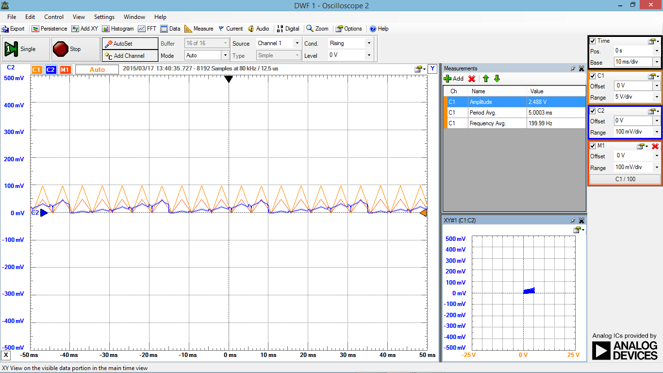
By connecting our circuit to a 2V, 2kHz sinusoidal current, a a 2V, 1kHz sinusoidal current, and a 4V, 100Hz triangular current, and then analyzing the output voltages with an oscilloscope, we were able to test our calculations. The results for each time-varying current pattern were as follows:
As the screenshots show, our predictions matched the true outcomes very closely. As a result, it is safe to say that output voltage in circuits containing alternating currents can be calculated using simple algebraic expressions that are functions of time.
BJT Curve Tracer Lab:
The second lab that we did in class today was an experiment designed to investigate the gain of a 2N3904 NPN transistor. By measuring the collector current vs. the collector voltage across different input voltages (by means of an oscilloscope), the gain was hoped to be experimentally determined. We hoped to utilize time-varying currents to gain accurate information about the gain across several different levels of current and voltage. After having tested the BJT, we then looked up the BJT's fact sheet, and compared the experimental values to the expected values to determine our precision within the experiment.
^^^^ Left: Resistance of the 100 Ohm Resistor. Right: Resistance of 100K Ohm Resistor ^^^^
^^^^ The constructed circuit, ready to be analyzed ^^^^


No comments:
Post a Comment